Restricted Earth Fault Relay Connection Diagram 35+ Pages Explanation Doc [2.2mb] - Updated 2021
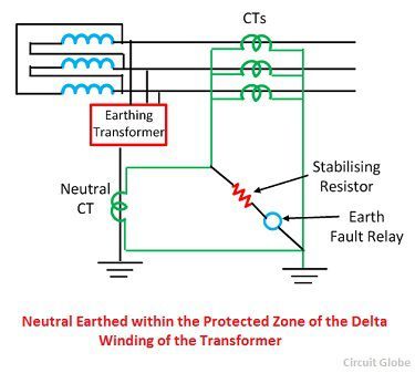
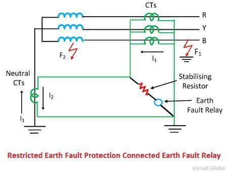
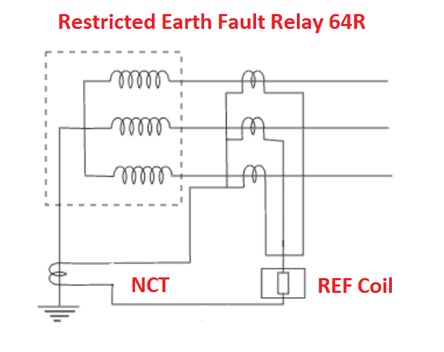
15+ pages restricted earth fault relay connection diagram 2.8mb. As shown in figure above there are a total of four Current Transformers CTs three CTs connected in each phase ie. The restricted earth fault relays are very sensitive for detecting internal faults. High impedance Restricted Earth Fault protection is the voltage based operating protection. Read also fault and learn more manual guide in restricted earth fault relay connection diagram The windings of many medium and small sized transformers are protected by restricted earth fault REF systems.
This relay protects the delta or unearthed star winding of the power transformer against the fault current. The earth fault protection scheme consists the earth fault relay which gives the tripping command to the circuit breaker and hence restricted the fault current.

Restricted Earth Fault Protection Of Transformer Ref Protection Electrical4u
| Title: Restricted Earth Fault Protection Of Transformer Ref Protection Electrical4u |
| Format: PDF |
| Number of Pages: 239 pages Restricted Earth Fault Relay Connection Diagram |
| Publication Date: February 2018 |
| File Size: 3mb |
| Read Restricted Earth Fault Protection Of Transformer Ref Protection Electrical4u |
 |
R Y and B and one CT connected in neutral.

Wiring Diagram Of Earth Fault Relay Full Hd Version Lamm Experts It Unrestricted Earth Fault Protection Working Priciple Electrical4u Connections Of Overcur Relay Part 2. The earth fault can be dispersed by using the restricted earth fault protection scheme. If the residual current is calculated the first group T1T2T3 shall be specified for the inputs of the three-phase current. Restricted Earth Fault Protection is also known as differentia. The restricted earth-fault stage operates exclusively on earth faults inside the area of protection. 31-1 Connection diagram for REF 542plus using four CTs For the restricted earth-fault protection to operate properly the REF 542plus shall be connected to residual and neutral current.

Restricted Earth Fault Protection System Explanation Working Circuit Globe
| Title: Restricted Earth Fault Protection System Explanation Working Circuit Globe |
| Format: ePub Book |
| Number of Pages: 228 pages Restricted Earth Fault Relay Connection Diagram |
| Publication Date: October 2021 |
| File Size: 2.2mb |
| Read Restricted Earth Fault Protection System Explanation Working Circuit Globe |
 |

A 4ct Connection Used In A Restricted Earth Fault Protection For A Download Scientific Diagram
| Title: A 4ct Connection Used In A Restricted Earth Fault Protection For A Download Scientific Diagram |
| Format: ePub Book |
| Number of Pages: 229 pages Restricted Earth Fault Relay Connection Diagram |
| Publication Date: August 2018 |
| File Size: 1.8mb |
| Read A 4ct Connection Used In A Restricted Earth Fault Protection For A Download Scientific Diagram |
 |

Ref Restricted Earth Fault Relay
| Title: Ref Restricted Earth Fault Relay |
| Format: ePub Book |
| Number of Pages: 303 pages Restricted Earth Fault Relay Connection Diagram |
| Publication Date: March 2018 |
| File Size: 810kb |
| Read Ref Restricted Earth Fault Relay |
 |

Restricted Earth Fault Protection System Explanation Working Circuit Globe
| Title: Restricted Earth Fault Protection System Explanation Working Circuit Globe |
| Format: ePub Book |
| Number of Pages: 233 pages Restricted Earth Fault Relay Connection Diagram |
| Publication Date: August 2019 |
| File Size: 2.3mb |
| Read Restricted Earth Fault Protection System Explanation Working Circuit Globe |
 |

Restricted Earth Fault Protection 64r Working Transformer Electrical4u
| Title: Restricted Earth Fault Protection 64r Working Transformer Electrical4u |
| Format: PDF |
| Number of Pages: 324 pages Restricted Earth Fault Relay Connection Diagram |
| Publication Date: March 2020 |
| File Size: 1.1mb |
| Read Restricted Earth Fault Protection 64r Working Transformer Electrical4u |
 |
High Impedance Protection Ct Connection For 5 Ct Arrangement Download Scientific Diagram
| Title: High Impedance Protection Ct Connection For 5 Ct Arrangement Download Scientific Diagram |
| Format: PDF |
| Number of Pages: 168 pages Restricted Earth Fault Relay Connection Diagram |
| Publication Date: June 2020 |
| File Size: 2.3mb |
| Read High Impedance Protection Ct Connection For 5 Ct Arrangement Download Scientific Diagram |
 |

What Is Restricted Earth Fault Relay 5 Ct Explanation
| Title: What Is Restricted Earth Fault Relay 5 Ct Explanation |
| Format: PDF |
| Number of Pages: 327 pages Restricted Earth Fault Relay Connection Diagram |
| Publication Date: October 2017 |
| File Size: 1.5mb |
| Read What Is Restricted Earth Fault Relay 5 Ct Explanation |
 |

Restricted Earth Fault Protection Of Transformer Ref Protection Electrical4u
| Title: Restricted Earth Fault Protection Of Transformer Ref Protection Electrical4u |
| Format: eBook |
| Number of Pages: 172 pages Restricted Earth Fault Relay Connection Diagram |
| Publication Date: July 2018 |
| File Size: 2.8mb |
| Read Restricted Earth Fault Protection Of Transformer Ref Protection Electrical4u |
 |
Restricted Earth Fault Protection
| Title: Restricted Earth Fault Protection |
| Format: eBook |
| Number of Pages: 148 pages Restricted Earth Fault Relay Connection Diagram |
| Publication Date: April 2017 |
| File Size: 3mb |
| Read Restricted Earth Fault Protection |
 |
Question On How To Connect Relay For Restricted Earth Fault Protection For 4 Wire System Wye Transformer Cr4 Discussion Thread
| Title: Question On How To Connect Relay For Restricted Earth Fault Protection For 4 Wire System Wye Transformer Cr4 Discussion Thread |
| Format: eBook |
| Number of Pages: 320 pages Restricted Earth Fault Relay Connection Diagram |
| Publication Date: July 2019 |
| File Size: 1.5mb |
| Read Question On How To Connect Relay For Restricted Earth Fault Protection For 4 Wire System Wye Transformer Cr4 Discussion Thread |
 |

Restricted Earth Fault Protection Of Transformer Ref Protection Electrical4u
| Title: Restricted Earth Fault Protection Of Transformer Ref Protection Electrical4u |
| Format: ePub Book |
| Number of Pages: 313 pages Restricted Earth Fault Relay Connection Diagram |
| Publication Date: January 2020 |
| File Size: 5mb |
| Read Restricted Earth Fault Protection Of Transformer Ref Protection Electrical4u |
 |
Restricted earth fault relay application within a 400kV shunt capacitor bank design Hydra Substation single line diagram As a result of the energization the Shunt Capacitor Bank SCB then experienced spurious trips. Restricted Earth Fault Operation Under normal conditions and by application of Kirchhoffs laws the sum of currents in both current transformers CTs equals zero. Restricted earth fault protection is kind of Zone protection.
Here is all you have to to know about restricted earth fault relay connection diagram CBCT ZCT are used to detect the leakage current in an Electrical Power System. A small amount of unbalance current leads to tripping of electrical equipment. In this video the philosophy behind the restricted Earth Fault Protection has been elaborated. Question on how to connect relay for restricted earth fault protection for 4 wire system wye transformer cr4 discussion thread a 4ct connection used in a restricted earth fault protection for a download scientific diagram high impedance protection ct connection for 5 ct arrangement download scientific diagram restricted earth fault protection system explanation working circuit globe ref restricted earth fault relay restricted earth fault protection The secondary of these four CTs are connected in parallel.


No comments:
Post a Comment